Automatic Street Lights using LDR and Relay
Have you ever wondered how the street lights automatically turn ON during night time and turn OFF during daytime? These street lights are coupled with a control circuit that senses the environment and then controls the street lights accordingly. One of the methods to control them is to use an LDR based circuit.
The circuit uses an NPN transistor to perform the switching action, this action is caused by the light falling upon the surface of the LDR.
Introduction -
In this post, we will learn to design an automatic street light control system that is based on LDR and an NPN transistor. This project can also be used as an emergency lighting device that turns on the battery-powered LEDs during power cuts.
In the circuit, the transistor acts as a switch and the LDR works as a darkness sensor. The relay has been used to connect the AC load to the system.
Note- The relay is used only to connect the AC load to the system, the circuit will still work without it (if you just want to turn ON/OFF LEDs).
Components Required -
1. LDR
2. 50k ohm Resistor
3. 220-ohm Resistor
4. NPN Transistor - BC547 or any equivalent
5. LED bulb
6. Relay + AC load (optional)
7. Power Supply (5v)
8. Connection Wires
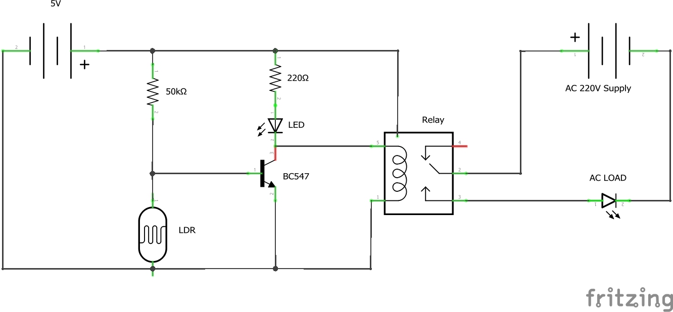
Circuit Schematic -
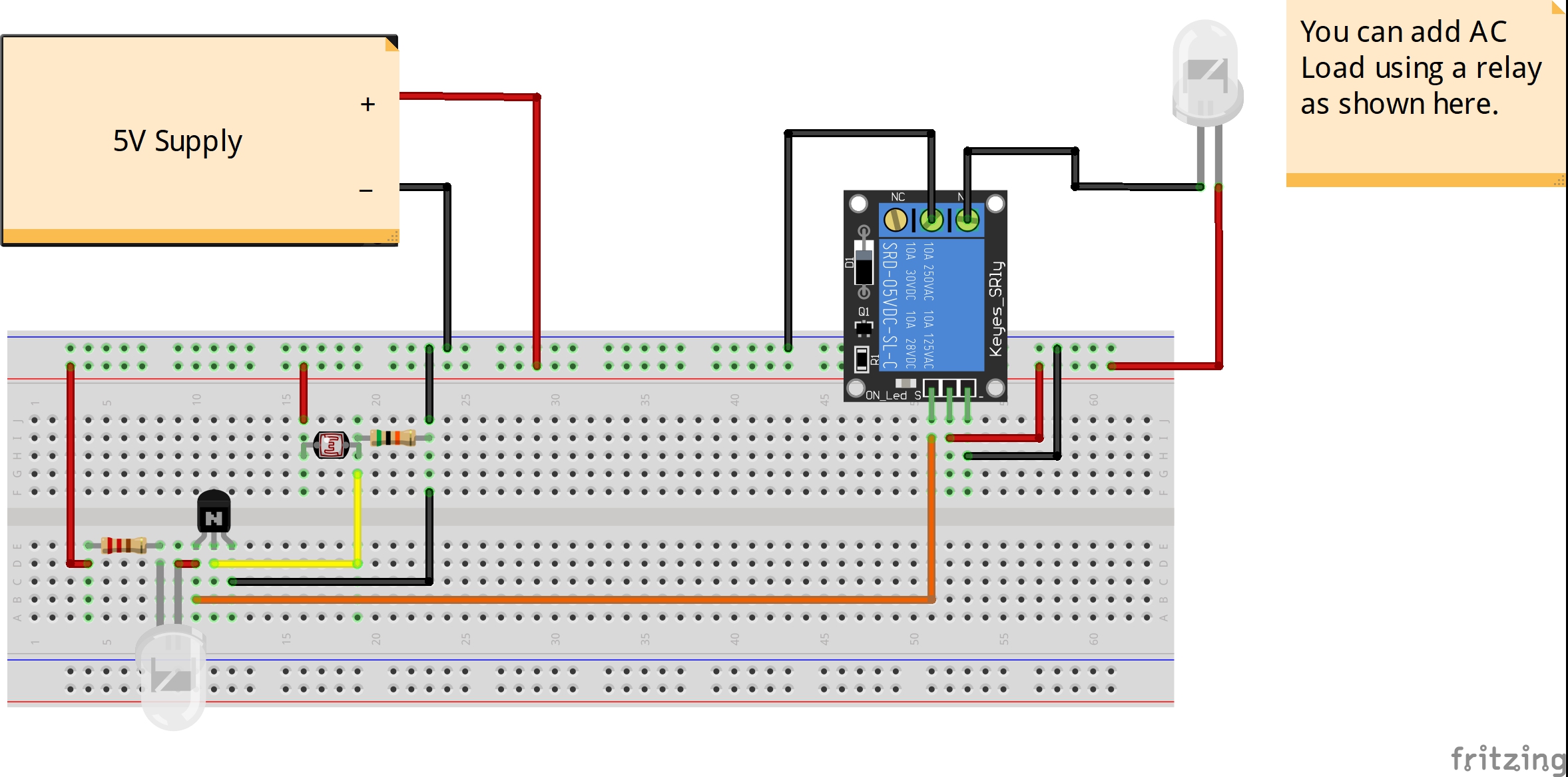
Connections-
1. Connect the 50K ohm resistor and the LDR in series between the +ve and -ve of the supply.
2. Connect the base of the transistor to the middle node of the LDR and resistor network as shown in the circuit diagram.
3. Connect the +ve terminal of the LED to the +ve of the supply through a 220-ohm resistor and the -ve of the LED to the Collector.
4. Connect the emitter of the transistor to the ground.
5. Connect the signal pin of the relay to the collector of the transistor and the power pins of the relay to the power supply.
6. Connect Phase/Live of the AC supply to COM terminal on the relay.
7. Connect the Neutral wire to one terminal of the load and connect the other terminal of the load to NO terminal of the relay.
What is an LDR?
LDR stands for Light Dependent Resistor, it is a resistor whose resistance change with the amount of light falling upon its surface. When the amount of light falling upon the LDR is high, the resistance decreases and when the amount of light is very low, the resistance increases.
What is a relay?
A relay is a device used to connect high voltage AC appliances to the control circuit. It provides isolation between the two circuits as the control circuit operates on DC and the load is working on AC. It has 3 terminals-
1. NO - Normally Open: It stays connected to the COM terminal when the relay is OFF.
2. NC - Normally Connected: It connects to the COM terminal only when the relay is ON.
3. COM - Common: It is the common terminal.
Working -
The LDR and the 50K ohm resistor forms a voltage divider network whose output depends upon the amount of light falling upon the surface of the LDR. During the day time, the resistance offered by the LDR is low due to which the voltage at the base terminal isn't enough to drive enough current through base of the transistor to turn it ON. But, during night time, the resistance of the LDR increases which also increases the potential at the base terminal due to this the transistor turns ON and the LED connected to the branch lights up.
The relay used in our circuit is a low-level triggered relay, which means it will only work when the signal pin is pulled low. When the transistor turns ON the signal pin is pulled LOW which turns ON the relay.
Voltage Divider Equation -
Vout = (R2 x Vin) / (R1+R2)
Warning - AC High voltages are lethal, be careful while making the connections.
How To Make Bootable Pendrive
Android 11 Release Road map with Date
Related post


0 comments
Leave a reply
Please Login or Register to Comment. Get StartedShare this article

Android 11 Release Road map with Date
